Design Guide
This Design Guide will help you receive the greatest value for your rollforming dollar. Here are some suggestions that take advantage of the benefits of roll-forming.
The process of Roll Forming introduces some potential distortions to consider. Watch this video clip to gain a better understanding of Curve, Twist and Bow – the typical causes, corrective actions and common tolerances.
- Roll forming video from Dalarna University:
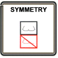
Design a symmetrical shape wherever possible. This allows an equal amount of forming to be done on each side of the vertical centerline, and equalizes the stresses imparted by the forming process as the strip progresses through the forming rolls.
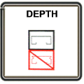
M. P. Metal Products suggests that you avoid cross sections with extreme deformations. The strains produced by rollforming (moving metal) are greatest around the arc of the bend and at the edges of the strip.
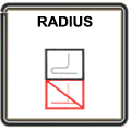
Try to avoid sharp bends. The ductility of the metal will determine the minimum bend radius possible. The rollformed radius should be at least equal to the metal thickness.
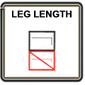
M. P. Metal Products recommends that the minimum practical leg length, including the bend, should be three times the metal thickness.
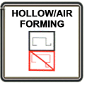
Whenever possible, avoid air forming (a bend or area that is not in direct contact with the rollforming tools). Dimensional accuracy is more difficult to control with this type of design.
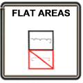
M. P. Metal Products suggests that when faced with wide, flat areas, consider adding ribs or grooves to hide potential waviness.
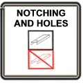
Try to position notches, slots, holes, etc., away from the bend line and the edge. Be aware that these openings may become distorted in size and shape during rollforming.
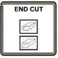
When a part is pre-cut (cut before rollforming), the leading end and trailing end are both likely to be distorted and flared. The pre-cut method may be advantageous to pocket areas and mitered edges.
In contrast, a part may be post-cut (cut after rollforming), with a flying cut-off die shaped to fit the profile. Post cutting produces somewhat less end cut distortion. This method is most common and efficient.
In contrast, a part may be post-cut (cut after rollforming), with a flying cut-off die shaped to fit the profile. Post cutting produces somewhat less end cut distortion. This method is most common and efficient.
Depending on the gage and metal tolerance, cross section tolerances of +/- .015 and angular tolerances of +/- 2 degrees are typical. Length tolerances of +/- 1/8" per 12 feet are routine. Tolerances may be designed tighter as required.
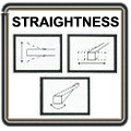
A) Bow and Camber: The deviation from a straight line in the vertical plane.
B) Lateral or curve or sweep: The deviation from a straight line in the horizontal plane.
C) Twist: The deviation from vertical and horizontal lines in a corkscrew shape: "propeller effect".
Bow and Lateral are typically held to +/- 1/8" per 10 feet. Twist is typically held to 5 degrees per 10 feet. These conditions can be caused by variations in metal hardness and thickness, by slitting pressures, burrs and stretching. Tighter tolerances can often be held with appropriate tooling design.

Spring back occurs when the elastic limit of the metal is not exceeded during a bending operation. In effect, the stock returns partially to its original pre-bent shape. Spring back can be countered by proper design of tooling that intentionally stretches the stock beyond the elastic limit and then, at another step, sets the correct shape by finish forming.
Contact Us
Please contact us for additional information regarding our services and capabilities.